Glad to hear a little crafty experimentation is happening. Can I help keep the head banging down a little?
From #26. And from what clucas stated. Once you understand a few thing that I found out over time, hopefully building your own encoder wheel might help you get it working faster and better.
Clucas stated that he converted from a Hall sensor to a reed switch. And his counts doubled. Understandable.
Reed switches for the most part just need a magnet close to them to open/close the "contacts".
Because his counts did double, that leads to understanding the basic hall sensor types. More on that in a minute.
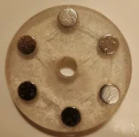
Your older magnet wheel encoders most probably used ceramic magnets. My dive into making a wheel sent me to buying a stack of 4mm diameter neodymiums.
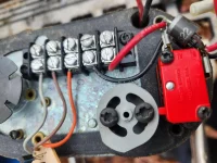
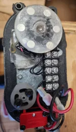
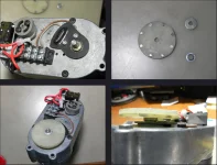
I used an old Houston Tracker hall sensor from and old (I think) Saginaw actuator and mounted it in a Superjack.
The wheel was just big enough to clear the inner workings of the original 6 pole ceramic disc magnet.
I used 20 magnets super glued evenly around the inside diameter of the disc. Used a sharpie to mark the side on them that was the same polarity. So all black sides faced up.
Here's where I lucked out. More on that soon.
All put together and the magnet wheel mounted to the actuator shaft gear shaft in place of the original magnet. Time to position it.
I wired everything on my bench. Gave the Hall sensor 5 VDC. Powered the actuator with my 12 VDC Harley battery.
Hooked my oscilloscope to the Hall sensor output lead an ground. Powered the actuator. Quickly found out that the Hall sensor was an 'open collector' output.
So put 5 VDC in series with the output terminal and ground lead of the sensor. If you have an actuator controller with reed switch sensor inputs, you should be able to measure DC voltage at those pins. Oscilloscopes aren't good at all measuring switch closures/resistance. They are voltage/time.
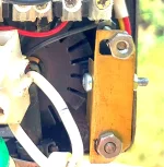
Alrightey. Next I positioned the hall sensor module close to the magnet wheel until I got a nice square wave. A bit....not perfect....some pulses were wider than others. "Design error" in spacing the magnets equally? Yeah that's the ticket. Somewhat. Once satisfied with the positioning of the sensor. I marked and drilled slotted holes (for wiggle room) in the gear cover plate and and mounted the sensor. More on that too.....
Let's call this part one.
Hall sensors come in several types. Some detect magnetic strength. Imagine being able to turn radio volume up by putting a magnet closer to the volume control. Or turning it down by pulling it away. Proximity. Not what we want. We need snap action like a toggle switch.
Some turn on and off when a magnet is brought close. No matter if the N or S pole is used. They get a magnetic field strong enough, they turn on. Pull it away, they turn off. We can use those types.
Some turn on when the N pole is brought close to them and turn off when the S pole is close. Meaning you could turn one on and take the magnet away....Hall would still stay on as long as it had power on the voltage supply. When you brought the S pole close, it turns off and stays that way. Most probable the type that was originally in clucas' unit.
So. If we want to build a Hall sensor encoder. A unipolar (magnet close, no matter which pole, turns on. Pull away, turns off) or a bipolar (turns on when one pole is brought close, and is forced off when the opposite pole is present). Those are the types needed.
Most all modern Hall switches have a Schmitt trigger output. Also very important. Gives a fast and positive action. Think of a snap action Lutron wall switch that clicks versus a Decora that "kind of" does.
Coffee, chores, more on this.

