
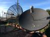
My actuator went fubar a long time ago, and I cant find parts for it, (OEM channel master, wheel cog for the reed switch) so all I did was move it tot the satellite with the HD NASA channel on it and fixed it in place, this until I find a replacement actuator that wont cut too deep into my budget.
Automatic Translations (Powered by Yandex):


Thread: Strong winds strip actuator
Results 21 to 30 of 38
-


 Legit Prodigy

- Join Date
- May 2016
- Posts
- 155
- Post Thanks / Like

 12-08-2023,01:19 PM

-
Post Thanks / Like - 2 Thanks, 0 Likes, 0 Kiss My Ass
-
 Advanced Tester
- Join Date
- Apr 2017
- Location
- South-Western Virginia
- Posts
- 179
- Post Thanks / Like
12-17-2023,06:39 PM
First attempt at magnet wheel pic below. Magnets are pressed into tight holes in middle plexiglass sheet. Thin plexiglass sheet is glued on each side. (Magnets entrapped) It may not show well in photo, but magnets are NOT perfectly spaced apart. Drill creep thru off the alignment.
I know I could just mount it to test. BUT, the wheel needs to be glued onto an optical disk. Be a PITA to glue it on, then have to remove it. Any ideas if this will be usable as is, or should I attempt to make another wheel with better spacing to begin with?
[Only registered and activated users can see links. ]
Any micro cracking shouldn't be an issue since three plexi sheets are glued together. (Many are heavy sanding scratches for a good bond, not cracks)
-
Post Thanks / Like - 1 Thanks, 0 Likes, 0 Kiss My Ass
 el bandido thanked for this post
-

 Open PLi

- Join Date
- Dec 2010
- Location
- Atlanta, Ga.
- Posts
- 8,288
- Post Thanks / Like
12-17-2023,08:38 PM
What you have to me looks good. Probably cannot do much better unless you get into a place that has equipment to make this stuff. Another thing to consider is whatever you do will probably be wrong. If you don't mount it, then you should have, and if you do mount it then you should not have.
My opinion is you should mount what you have already assembled and see how it does or does not work. It might work fine like it is for what you need it to do.
[Only registered and activated users can see links. ]
-
Post Thanks / Like - 1 Thanks, 0 Likes, 0 Kiss My Ass
armadillo_115 thanked for this post
-
 Honoured Tester
- Join Date
- Dec 2019
- Location
- Lompoc, CA
- Posts
- 29
- Post Thanks / Like
12-17-2023,11:00 PM
My first actuator had magnets that alternated polarity N then S, N then S, etc. on the wheel. The sensor screwed into a white plastic mount so that it could be adjusted in or out to miss the rotating wheel. The sensor failed and I replaced it with a reed switch in a glass tube by soldering #14 copper wire to each end. The wire was stiff enough to hold it all in place. Worked fine but my count doubled which was an added benefit for Ku. I guess back then the magnet would either pull on the internal workings of the switch then push it out assuring full motion of the switch.
-
Post Thanks / Like - 2 Thanks, 0 Likes, 0 Kiss My Ass
-
Advanced Tester
- Join Date
- Apr 2017
- Location
- South-Western Virginia
- Posts
- 179
- Post Thanks / Like
12-17-2023,11:45 PM
After thinking some more: I can temporarily mount this with a hot glue gun. Center only. Shouldn't be too hard to remove if necessary.
First; I'd like to rig up a AAA battery and light bulb circuit to determine the distance to mount the sensor. Visualize what is going on since I don't have high-tech test equipment. I will have to build a sensor mount from scratch. (Maybe make it adjustable) I believe these little magnets are too strong, but embedding them in the plexiglass will lessen their strength. Plus the magnets will never drop off.
I plan to bring actuator inside the house to do the testing. Weather too unreliable to do much outdoors.
-
Advanced Tester
- Join Date
- Apr 2017
- Location
- South-Western Virginia
- Posts
- 179
- Post Thanks / Like
12-17-2023,11:59 PM
One of these actuators had a 4 magnet wheel, but NO sensor or bracket. Not sure how the magnets were orientated since they jumped out of place when I removed it from the shaft. Magnets are large in diameter and I don't believe they would function with the double count switch I bought. Originally Posted by clucas

I could have tried a single count switch with this magnet wheel.... but didn't want to be limited to only a four count wheel. If my homemade wheels don't work, it may be a fallback option. (Or I could remove the large magnets and glue my small magnets in their place, and use a new double count sensor.)
Time will tell.
-
Advanced Tester
- Join Date
- Oct 2019
- Posts
- 134
- Post Thanks / Like
12-19-2023,10:07 AM
Glad to hear a little crafty experimentation is happening. Can I help keep the head banging down a little?
From #26. And from what clucas stated. Once you understand a few thing that I found out over time, hopefully building your own encoder wheel might help you get it working faster and better.
Clucas stated that he converted from a Hall sensor to a reed switch. And his counts doubled. Understandable.
Reed switches for the most part just need a magnet close to them to open/close the "contacts".
Because his counts did double, that leads to understanding the basic hall sensor types. More on that in a minute.
Your older magnet wheel encoders most probably used ceramic magnets. My dive into making a wheel sent me to buying a stack of 4mm diameter neodymiums.
I used an old Houston Tracker hall sensor from and old (I think) Saginaw actuator and mounted it in a Superjack.
The wheel was just big enough to clear the inner workings of the original 6 pole ceramic disc magnet.
I used 20 magnets super glued evenly around the inside diameter of the disc. Used a sharpie to mark the side on them that was the same polarity. So all black sides faced up.
Here's where I lucked out. More on that soon.
All put together and the magnet wheel mounted to the actuator shaft gear shaft in place of the original magnet. Time to position it.
I wired everything on my bench. Gave the Hall sensor 5 VDC. Powered the actuator with my 12 VDC Harley battery.
Hooked my oscilloscope to the Hall sensor output lead an ground. Powered the actuator. Quickly found out that the Hall sensor was an 'open collector' output.
So put 5 VDC in series with the output terminal and ground lead of the sensor. If you have an actuator controller with reed switch sensor inputs, you should be able to measure DC voltage at those pins. Oscilloscopes aren't good at all measuring switch closures/resistance. They are voltage/time.
Alrightey. Next I positioned the hall sensor module close to the magnet wheel until I got a nice square wave. A bit....not perfect....some pulses were wider than others. "Design error" in spacing the magnets equally? Yeah that's the ticket. Somewhat. Once satisfied with the positioning of the sensor. I marked and drilled slotted holes (for wiggle room) in the gear cover plate and and mounted the sensor. More on that too.....
Let's call this part one.
Hall sensors come in several types. Some detect magnetic strength. Imagine being able to turn radio volume up by putting a magnet closer to the volume control. Or turning it down by pulling it away. Proximity. Not what we want. We need snap action like a toggle switch.
Some turn on and off when a magnet is brought close. No matter if the N or S pole is used. They get a magnetic field strong enough, they turn on. Pull it away, they turn off. We can use those types.
Some turn on when the N pole is brought close to them and turn off when the S pole is close. Meaning you could turn one on and take the magnet away....Hall would still stay on as long as it had power on the voltage supply. When you brought the S pole close, it turns off and stays that way. Most probable the type that was originally in clucas' unit.
So. If we want to build a Hall sensor encoder. A unipolar (magnet close, no matter which pole, turns on. Pull away, turns off) or a bipolar (turns on when one pole is brought close, and is forced off when the opposite pole is present). Those are the types needed.
Most all modern Hall switches have a Schmitt trigger output. Also very important. Gives a fast and positive action. Think of a snap action Lutron wall switch that clicks versus a Decora that "kind of" does.
Coffee, chores, more on this.
-
Post Thanks / Like - 0 Thanks, 1 Likes, 0 Kiss My Ass
 armadillo_115 liked this post
-
Advanced Tester
- Join Date
- Apr 2017
- Location
- South-Western Virginia
- Posts
- 179
- Post Thanks / Like
12-22-2023,08:25 PM
Any ideas how to set the Limits on this Uniden actuator? (Von Weise) I'm not familiar with this type. I see where it can be set... but that looks to me like it will only work for one direction. Or am I missing something? If only one limit... I will set it for maximum safe extension. *Picture taken before reed switch conversion
[Only registered and activated users can see links. ]
Actuator has been briefly tested OFF the dish. Counts are flying in both directions, so it should give many counts between Sats. How accurate/precise it will be remains to be seen. Hope to install it tomorrow if everything goes as planned.
Thanks for all assistance!
-
Post Thanks / Like - 1 Thanks, 1 Likes, 0 Kiss My Ass
el bandido thanked for this post
el bandido liked this post
-
Advanced Tester
- Join Date
- Oct 2019
- Posts
- 134
- Post Thanks / Like
12-23-2023,11:58 AM
Pretty easy. The stacked microswitches and cams control the limits. From the factory the lower limit is usually already set. That's the lower cam. It's non-adjustable (unless you loosen the geartrain cover plate to disengage the gear that drives the cam). So from the factory the actuator tube is retracted all the way in (shortest) and then turned out several turns. I choose 6 full turns when setting mine up.
The upper cam is for the extended limit. Loosening the top 2 screws and lifting the cam and turning it to adjust the upper limit. Then engaging the stepped cam coupling to the lower cam and tightening the screws. You adjust it so that the upper microswitch 'just' clicks.
Of course you need to be aware of which way the cam turns when it extends/retracts.
There are cases like when you remove the gear drive from the tube that the lower limit cam will get off kilter.
Just unbolt the motor from the tube. Drive the motor to it's lower electrical limit until it shuts off. Retract the tube with a pair of Vice Grips. Spin it out, oh let's say 6 turns. And reinstall the motor.
Then you will want to verify that the upper limit is still set right.
There will be some times that the limit cams "jump right past" the microswitch and the motor keeps running. Like if a switch gets dirty or is failing, the plunger is worn.
You could get fooled and flustered because what seems to be is totally "off". Because the cam needs to rotate to the opposite side of the switch plunger. That's where loosening the gearcase cover and turning the cam gear would be needed.
-
Post Thanks / Like - 2 Thanks, 1 Likes, 0 Kiss My Ass
armadillo_115 liked this post
-
Advanced Tester
- Join Date
- Apr 2017
- Location
- South-Western Virginia
- Posts
- 179
- Post Thanks / Like
12-23-2023,07:53 PM
Thanks Arlo!
After looking at it better with my glasses on today I 'discovered' that lower limit.") And yes, it was preset for the retraction. I adjusted the upper limit with plenty of margin for error. Will determine exactly where it needs to be later.
And yes, it was preset for the retraction. I adjusted the upper limit with plenty of margin for error. Will determine exactly where it needs to be later.
Actuator is mounted!
On the west side and pushing up as previous one. (This dish only needs to cover the western arc) Sats are programmed in from 135w to 116w so far. Done messing with it today. Mama wants her PanAmericana NOW!. lol
135w to 116w = 19 degrees.
135w to 116w = 291 counts
15.3 counts per degree Which is higher count # than I ever had before.
I will need to slide the actuator down at the clamp 2 or 3 inches to maximize the throw. Ran out of daylight today. Finished wiring the motor wires using the cellphone light.
Whether the count positions remain accurate over time remains to be seen.


-
Post Thanks / Like - 1 Thanks, 1 Likes, 0 Kiss My Ass
el bandido thanked for this post
el bandido liked this post


Posting Permissions
- You may not post new threads
- You may not post replies
- You may not post attachments
- You may not edit your posts

vBulletin Optimisation provided by vB Optimise (Lite) - vBulletin Mods & Addons Copyright © 2024 DragonByte Technologies Ltd. Runs best on HiVelocity Hosting.
Donation System provided by vBDonate (Lite) - vBulletin Mods & Addons Copyright © 2024 DragonByte Technologies Ltd.
Shoutbox provided by vBShout (Lite) - vBulletin Mods & Addons Copyright © 2024 DragonByte Technologies Ltd.
Feedback Buttons provided by Advanced Post Thanks / Like (Lite) - vBulletin Mods & Addons Copyright © 2024 DragonByte Technologies Ltd.
Copyright © LegitFTA.com 2010 - 2024 Hands Off